
|
Wave2000 Example #1:
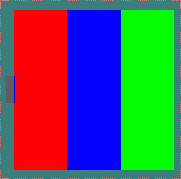
Layered media measurements using pulse-echo ultrasound.The figure below and associated legend represent a layered ultrasound propagation problem. Wave2000 has a pseudo-color display related to material definitions which is shown here. Thus, in this model there are three material layers making up the overall object, aluminum, titanium and chromium, going from left to right across the screen. Also shown is a 0.5 cm transducer located at the center of the left side of the object. This transducer has been defined in Wave2000 to operate in pulse-echo mode.


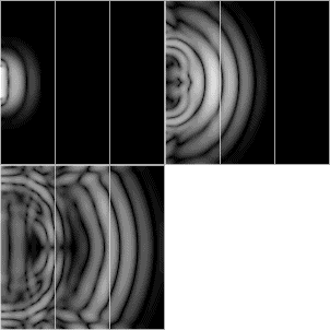
Wave2000 generates "step-by-step" images of the propagating ultrasound wave. The ultrasound "movie" below displays a 1 MHz sine wave with a Gaussian envelope propagating into the layered structure from the left surface. The diffraction spreading of the wave from the transducer can be seen, while the wave is reflected and transmitted at the boundaries of the layers. The boundaries are displayed as a light pixel value proportional to the gradient between the two regions.

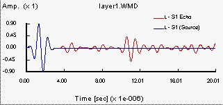
Wave2000 plots and/or saves all transducer source and/or receiver data. The figure below displays a receiver plot associated with this layered simulation model. The graph shows the measurements associated with the pulse-echo receiver. As may be seen, the source waveform (in blue) is displayed at the very beginning of the plotted signal. The reflected waveform measured by the receiving portion of the pulse-echo transducer is shown in red. On this curve, the first identifiable waveform is the reflection from the first (aluminum/titanium) interface, occurring at about 4 us. Following that, the next main portion of the waveform is the reflection associated with the second (titanium/chromium) interface, occurring at about 8 us. The last well defined reflection is that associated with the vacuum portion of the object (i.e., the reflection associated with the chromium/vacuum interface at the right side of the object), and occurs at about 11 us. You can also observe the presence of later arriving signal energy, representing multiple reflections as well as mode conversions. Note that the stated arrival times are the round trip travel times for the ultrasound signals.

In Wave2000, ultrasound simulations can be easily adapted to model various changes to the interrogated object. For example, Wave2000 can model the effects of non-parallel material layers as easily as it simulates this parallel interface model. It is interesting to note in this example that the source transducer gives rise to a significant amount of diffraction spreading and as a result a related amount of non-normal incidence of the ultrasonic wavefront onto the boundaries (and the associated shear waves generated by mode conversion). These phenomena are all accounted for in a Wave2000 simulation.
|
|||||||||
© 2024 CyberLogic, inc. All Rights Reserved